This article covers configuring and wiring IBR 600/900, 1100, 1700, R1900, and R920 series routers for R2V and R2R solutions.
There are six steps to activate a Cradlepoint-equipped vehicle on HAAS Alert's Safety Cloud platform:
- Upload HAAS Alert's Cradlepoint application via NetCloud Manager
- Create a Group(s) via NetCloud Manager only if you don't have any groups already
- Update the Group(s) configuration(s) via NetCloud Manager
- Assign the HAAS Alert app to each Group
- Assign routers to the appropriate Group(s) via NetCloud Manager
- Connect vehicle wiring to the Cradlepoint Router
Step 1 - Upload HAAS Alert's Cradelpoint application via NetCloud Manager
HAAS Alert will provide you with a file with the "tar.gz" file format - the application controls when vehicle information is sent to Safety Cloud. Download this file to your computer.
In the main menu on the left, click "TOOLS." Then check "Enable NCOS SDK."
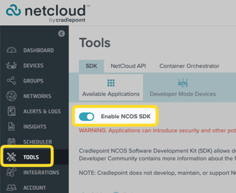
Under the "Available Apps" section, if an existing application exists in the list, STOP IMMEDIATELY and contact HAAS Alert.
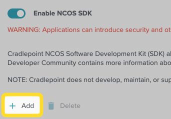
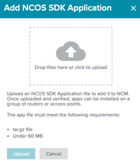
If no items are listed, click "Add." Drag or select the "zar.gz" file HAAS Alert emailed into the upload box, then click Upload.
.
Step 2 - Create a Group(s) via NetCloud Manager
If you already use "Groups" in NetCloud Manager, skip to Step 3
The purpose of a Group is to both (a) upload the HAAS Alert application to the routers and (b) apply the same configuration settings to all routers in the same Group. This will save you time during the setup process for fleets with more than a few routers.
HAAS Alert requires the following configuration settings to be applied to each router via a Group template:
- HAAS Alert application configuration settings
- Router GPIO default settings
- Location Services (must be enabled)
For smaller fleet sizes, one Group can be utilized (the HAAS Alert Safety Cloud Dashboard can be used to update the vehicle type). For larger fleet sizes, it is recommended to create a separate Group for each group of similar vehicles (e.g., one Group for fire trucks and one Group for ambulances). The HAAS Alert support team will provide you with a recommendation.
If you have different models of routers, you need to create a separate Group for each router model.
If your routers have different NetCloud OS versions, you should upgrade to the same version, or you will need to create a separate Group for each NetCloud OS version.
To create a Group:
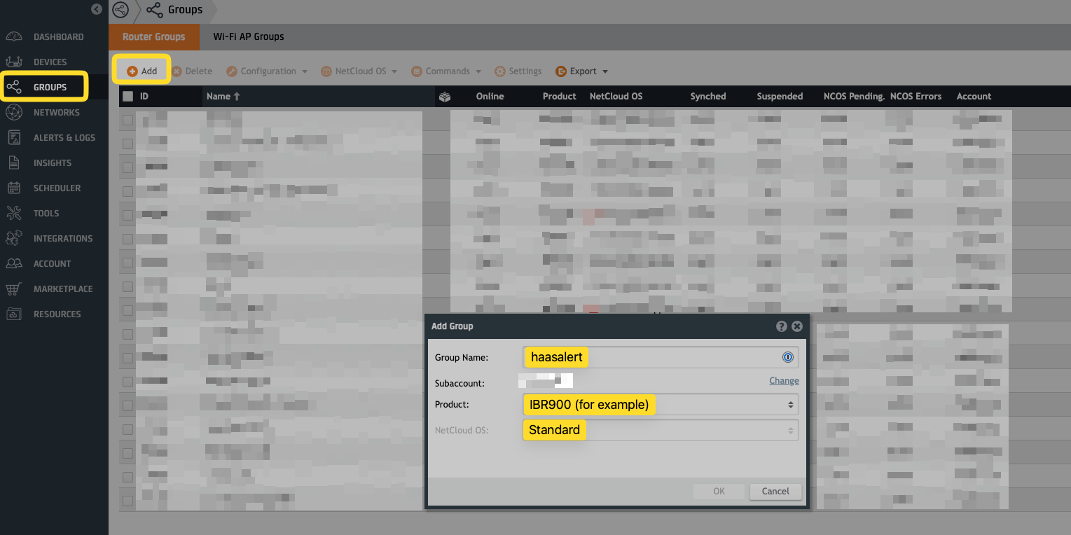
- In the main menu on the left, click "GROUPS."
- Click "+ Add" in the top left to create a new group for HAAS Alert.
- Enter "haasalert" for the "Group Name" (or "haasalert-fire" and "haasalert-ems" for multiple Groups).
- Select your router model (e.g., "IBR900") for the "Product."
- Choose "Standard" for the "NetCloud OS Type."
- Select the "NetCloud OS" version your routers are using - if your routers use different NetCloud OS versions, upgrading them to the same version is recommended.
Step 3 - Update the Group(s) Configuration(s)
In this Step, you will need to apply the following updates to all Groups (either the new ones created in Step 2 or existing ones in your account) that contain routers you are activating on HAAS Alert's platform:
- HAAS Alert application configuration settings
- Router GPIO default settings
- Location Services (must be enabled)
Step 3a - Configuration File
Open the Configuration File provided by HAAS Alert for the selected router. The file will have a ".txt" extension.
Select all text in this file and Copy it to your computer (i.e., CTRL-C or ⌘-C)
Important: Validate that the text is formatted properly
Go to https://jsonlint.com
Paste the copied text into the large white box and then click "Validate JSON"
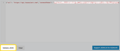
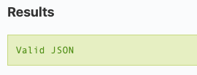
If you see "Valid JSON," proceed to Step 3b. If you see any other message, stop and contact HAAS Alert.
Step 3b - Configuration Settings (Option 1)
Login to NetCloud Manager (https://www.cradlepointecm.com/) as a user with Admin rights
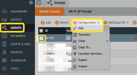
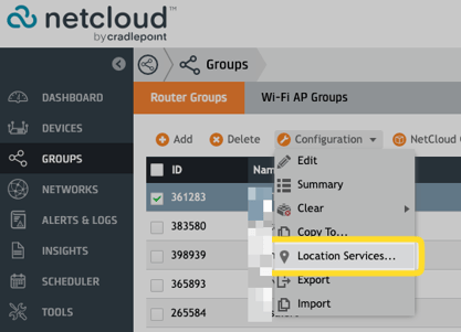
In the left menu, click "GROUPS." You will see a list of all existing Groups. Tick the box(es) next to the Group(s) you created for HAAS Alert. That Group(s) should be highlighted.
In the menu at the top, click "Configuration" and select "Edit" in the dropdown list.
In the pop-up window's left menu, click "NETWORKING" then "Local Networks" then "Hotspot Services."
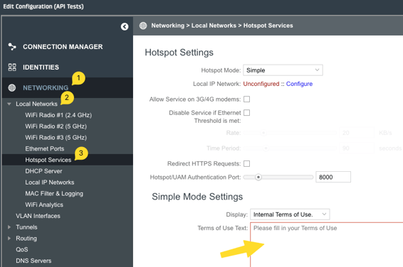
If the Terms of Use Text box is NOT empty, skip to Step 3c now
If the Terms of Use Text box IS empty:
- Paste the copied text from Step 3a into this box
- Scroll down and click the "Save" button. Do NOT click "Commit Changes."
- Continue with Step 3d
Step 3c - Configuration Settings (Option 2)
Skip this step if you completed Step 3b
In the left menu, click "GROUPS." You will see a list of all existing Groups. Tick the box(es) next to the Group(s) you created for HAAS Alert. That Group(s) should be highlighted.
In the menu at the top, click "Configuration" and select "Edit" in the dropdown list.
In the pop-up window's left menu, click SYSTEM, IoT, then Microsoft Azure IoT Central.
If the Scope ID box is NOT empty, STOP and contact HAAS Alert.
If the Scope ID box IS empty, then:
- Paste the copied text from Step 3a into this box
- Scroll down and click the "Save" button. Do NOT click 'Commit Changes.'
Step 3d - GPIO Wire(s) Configuration
In the Configuration Window menu, click "SYSTEM" then "GPIOs."
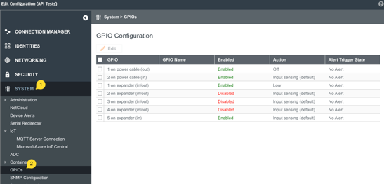
Tick the box next to the GPIO port connected to the vehicle's warning lights switch.
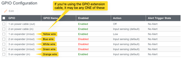
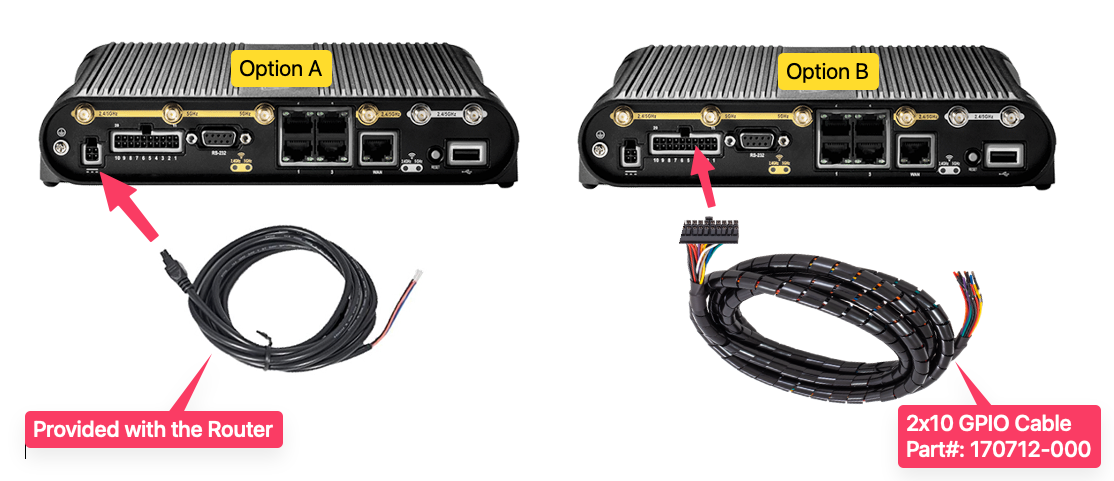
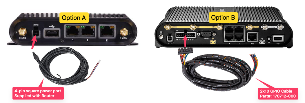
There are two cable options depending on your router. You may have the default 4-pin square power port or the optional GPIO extension cable. It is important to know which you're using for this step.
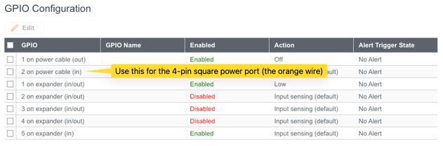
If your vehicles use Cradlepoint's "Ignition Sensing," the orange wire on the 4-pin square power port is most likely used, and you will need to use the GPIO extension cable to connect to the warning lights.
In the pop-up window, select: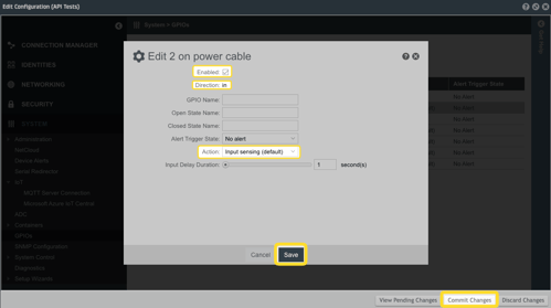
- 'Enabled' = checked
- 'Direction' = "In"
- 'Action' = "Input Sensing"
Click "Save."
If you are NOT activating HAAS Alert's Responder-to-Responder (R2R) safety service (i.e., visual alerts inside your vehicles via HAAS Alert LEDs):
- Click "Commit Changes"
- Skip to Step 3e
Configure R2R (if applicable)
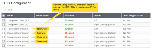
If you ARE activating HAAS Alert's R2R safety service, tick the box next to the GPIO port connected to the R2R LEDs.
There are two cable options depending on your router. You may have the default 4-pin square power port or the optional GPIO extension cable. It is important to know which you're using for this step.
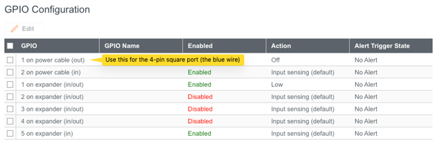
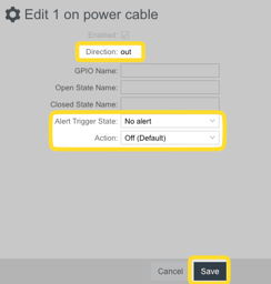 In the pop-up window, ensure:
- Direction: out
- Alert Trigger State: No alert
- Action: Off (Default)
Click "Save."
Click "Commit Changes."
In the pop-up window, select: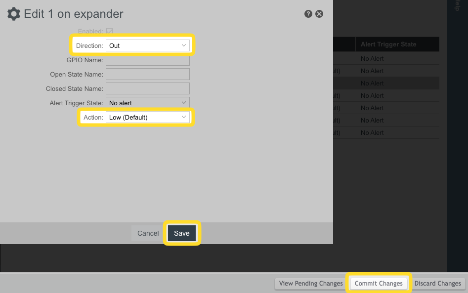
- 'Direction' = "Out"
- 'Action' = "Low (Default)"
Click "Save."
Click "Commit Changes."
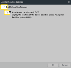
Step 3e - Enable Location Services
In the left menu, click "GROUPS." You will see a list of all existing Groups. Tick the box(es) next to the Group(s) you created for HAAS Alert. That Group(s) should be highlighted.
In the menu at the top, click "Configurations" and select "Location Services..." in the dropdown list.
Tick the box next to 'Enable Location Services' and tick the radio button next to 'Last Known Location." Then click OK.
Repeat Step 3e for all Groups with routers you are activating with HAAS Alert.
Step 4 - Assign HAAS Alert Application to Group(s)
In the main menu on the left, click 'GROUPS.'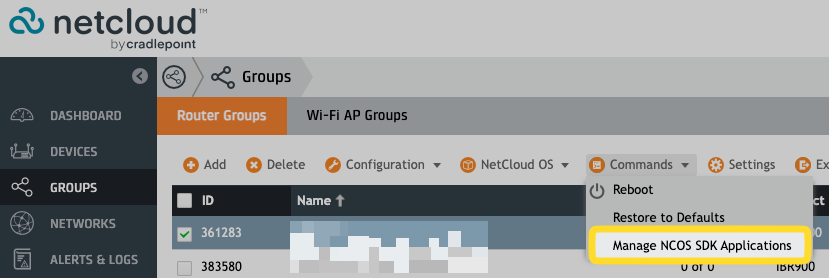
Tick the box next to one of the Groups you created earlier.
Click "Commands" in the top menu bar. Select "Manage NCOS SDK Applications."
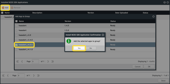
In the open window, click "Add" in the top left. This will open a window listing all the Apps available in NetCloud Manager.
Select the 'haasalert' App and click "OK" in the bottom right. A confirmation window will appear, confirming your request to add the "haasalert" App to the Group. Select "Yes."
Repeat Step 4 for all Groups with routers you activate with HAAS Alert.
Step 5 - Assign Routers to the "haasalert" Group
Only perform Step 5 if you created new groups earlier in Step 2. Otherwise, no further action is required.
In the main menu on the left, click "DEVICES."
Tick the box next to all the routers you would like to assign to the same Group.
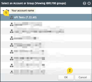
Click "Move" in the top menu.
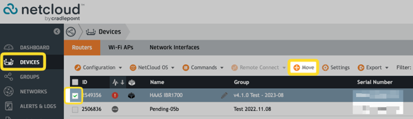
In the pop-up window, select the appropriate Group, then click "OK."
At this point, the "haasalert" App is in the process of being downloaded to the routers in the Group.
Repeat Step 5 for all NEW groups with routers you are activating with HAAS Alert.
No further action is required.
Step 6 - Connect Vehicle Wiring to the Cradlepoint Router
Step 6a describes connecting the vehicle's warning lights to the Cradlepoint router.
Step 6b describes how to connect the Cradlepoint router to the HAAS R2R safety service (if applicable)
More wiring instructions may be found on Cradlepoint's knowledge base website, Cradlepoint Connect: https://customer.cradlepoint.com/s/article/Cradlepoint-GPIO-Reference.
Step 6a - Hardwire Vehicle's Warning Lights Switch to the Cradlepoint Router
Choose your router:
R1900 Series Routers
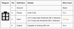
 With Option A, the orange wire (Input / Pin 3) must be connected to the positive side of the warning lights switch. You must use a different option if the orange wire is already used. For HAAS Alert's Responder-to-Responder (R2R) safety service, you may use the blue wire (Output / Pin 4) from the power cord to trigger the R2R LED indicator.
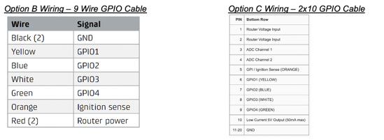
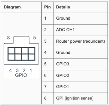 With Option B, connect the GPIO 1, GPIO 2, or GPIO 3 (Pins 7, 6, or 5) on the GPIO extension cable to the positive side of the warning lights switch. For HAAS Alert's Responder-to-Responder (R2R) safety service, one of the remaining GPIO 1, GPIO 2, or GPIO 3 (Pins 7, 6, or 5) will be used to trigger the R2R LED indicator.
It is important to know which wire is connected to the warning lights for Step 3D.
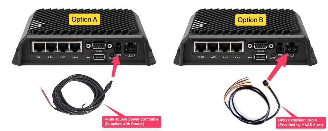
IBR1700 Series Routers
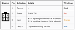
 If Option A, the orange wire (Input / Pin 3) must be connected to the positive side of the warning lights switch. You must use a different option if the orange wire is already used. For HAAS Alert’s Responder-to-Responder (R2R) safety service, you may use the blue wire (Output / Pin 4) from the power cord to trigger the R2R LED Indicator.
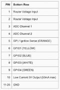 If Option B, connect the orange (preferred), yellow, blue, white, or green wire on the GPIO extension cable to the positive side of the warning lights switch. The remaining GPIO pins can be used for the R2R safety service.
It is important to know which wire is connected to the warning lights for Step 3D.
IBR900 / IBR600 Series Routers
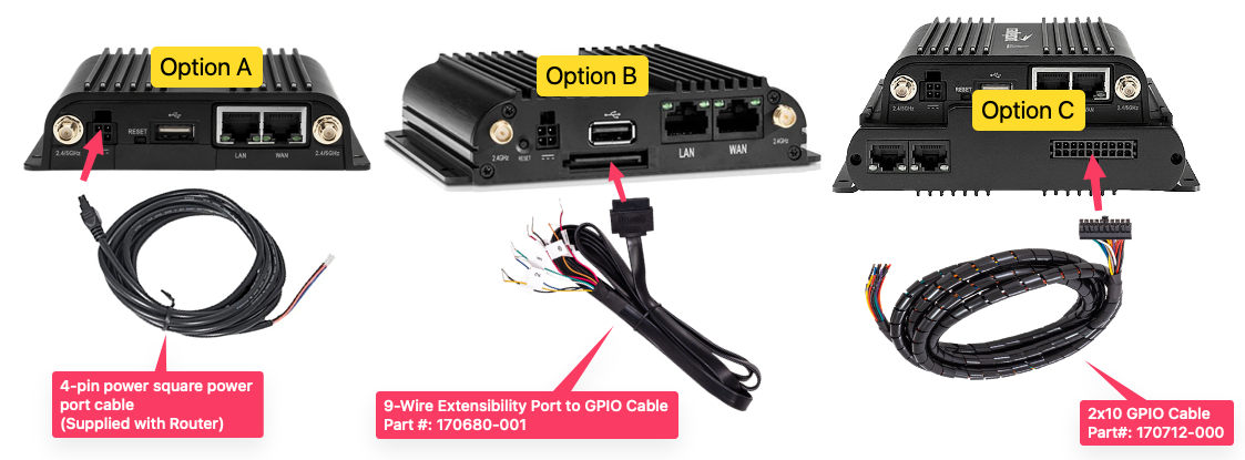
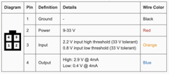 If Option A, the orange wire (Input / Pin 3) must be connected to the positive side of the warning lights switch. If the orange wire is already in use, then you must use a different option. For HAAS Alert’s Responder-to-Responder (R2R) safety service, you may use the blue wire (Output / Pin 4) from the power cord to trigger the R2R LED Indicator.
If Option B or Option C, connect either the orange (preferred), yellow, blue, white, or green wire on the GPIO extension cable to the positive side of the warning lights switch. Any of the remaining GPIO pins can be used for the R2R safety service.
It is important to know which wire is connected to the warning lights for Step 3D.
R920 Series Routers
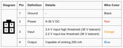 If Option A, the orange wire (Input / Pin 3) must be connected to the positive side of the warning lights switch. You must use a different option if the orange wire is already used. For HAAS Alert’s Responder-to-Responder (R2R) safety service, you may use the blue wire (Output / Pin 4) from the power cord to trigger the R2R LED Indicator alert.
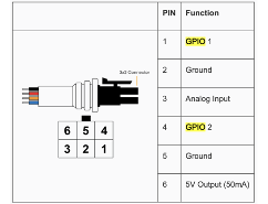 If Option B, connect the GPIO 1 or GPIO 2 (Pins 1 or 4) on the GPIO extension cable to the positive side of the warning lights switch. If the R2R safety service is being used, the other wire, GPIO 1 or GPIO 2 (Pins 1 or 4), will be used to trigger the R2R LED Indicator alert.
It is important to know which wire is connected to the warning lights for Step 3D.
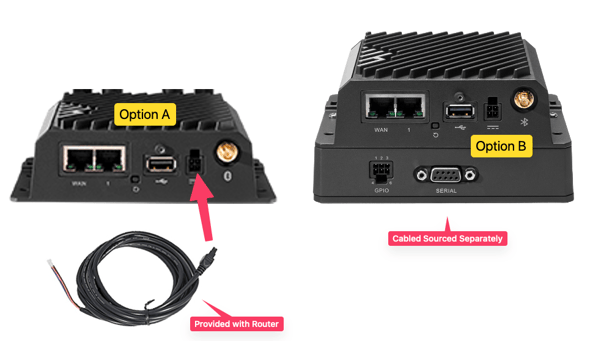
IBR1100 Series Routers
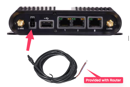
The IBR1100 series router can connect your vehicle’s warning lights via the 4-pin square power port and power cable.
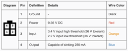 The orange wire (Input / Pin 3) must be connected to the positive side of the warning lights switch. You must use a different option if the orange wire is already used. For HAAS Alert’s Responder-to-Responder (R2R) safety service, you may use the blue wire (Output / Pin 4) from the power cord to trigger the R2R LED Indicator alert.
It is important to know which wire is connected to the warning lights for Step 3D.
Step 6b - Responder-to-Responder (R2R) Wiring
Skip to Step 2 if you are not using the R2R Safety Service
The following components must be installed in your vehicle for the R2R safety service:
- 3-Conductor Cable (30-ft)
- Splitter Box
- 10-ft Ethernet Cables (Qty 2, not shown)
- R2R LED Indicators (Qty 2)
3-Conductor Cable (30-ft) (aka R2R Cable)
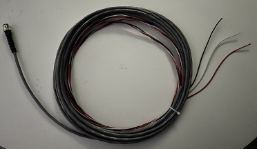 Cable with three copper wires to provide +12V power, ground, and the LED 'trigger' from the Cradlepoint router. One end of this cable terminates with a male M12 connector that screws into the y-cable or Splitter Box.
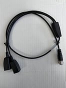
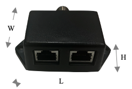
Y-Cable or Splitter Box
 .
.
You may receive one of the two options above. The y-cable (first image) is most commonly provided.
The y-cable has a female M12 connector on one end that screws into the 3-Conductor Cable (see above) and 2 RJ45 ports for connection to the ethernet cables.
The hard plastic splitter with a female M12 connector on one end that screws into the 3-Conductor Cable (see above) and 2 RJ45 ports for connection to the ethernet cables. Includes two screw holes for secure installation.
Plastic splitter dimensions (L x W x H): 2.87" (including screw holes) x 1.53" x 0.98" (M12 connector adds 0.55").
One of the RJ45 ports will remain unused when using a single LED indicator. The ports are universal; therefore, either one may be used while leaving the other open.
10-ft Ethernet Cables (Qty 2, not shown)
Each cable plugs into one port on the Splitter Box (see above) and into one of the R2R LED indicators (see below).
R2R LED Indicators (Qty 2)
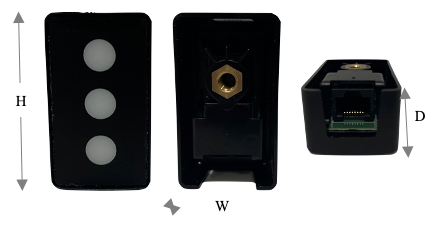 A molded, hard plastic rectangular box containing 3 LEDs that illuminate when it receives the trigger signal from the Cradlepoint router. A standard 1/4-20 threaded screw hole in the back for secure mounting. Mounting hardware is included.
Dimensions (H x W x D): 2.28" x 1.33" x 0.95".
For those vehicles that are using the R2R safety service, there are two different wiring options. See below for Option A or Option B
Option A: Use the BLUE wire on the 4-pin square power cable
Option B: Use any one of the available wires on the GPIO cable (cable varies by router model type)
The Cradlepoint router sends an output signal to trigger LEDs to illuminate when Safety Cloud detects a possible collision with another responding emergency vehicle.
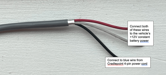
HAAS Alert provides a 3-conductor cable with a red, black, and white wire inside (“R2R Cable”). This cable provides +12V power, ground, and the “trigger” to the LEDs. It is recommended to use a 1A or 2A fuse.
Connect the Cradlepoint cable to the R2R Cable as follows:
Option A
- Connect BOTH the red and white wires from the R2R Cable to the vehicle's +12v constant battery or ignition power.
- Connect the black wire from the R2R Cable to the blue wire from the Cradlepoint 4-pin square power cord.
Option B
- Connect the red wire from the R2R Cable to the vehicle's +12V constant battery or ignition power.
- Connect the black wire from the R2R Cable to the vehicle ground.
- Connect the white wire from the R2R Cable to one of the GPIO1 - GPIO4 cables connected to the Cradlepoint router.
Option A or Option B's other end of the R2R Cable with the circular, screw-on M12 connector should be connected to the splitter box included in the HAAS Alert R2R LED Indicator kit.
It is important to know which R2R wiring option was used for Step 3d.